LOOSE TUBE OPTICAL FIBER CABLE
Short Description:
OPTICAL FIBER CABLE TECHNICAL STANDARD
PRODUCT DESCRIPTION
OPTICAL FIBER CABLE TECHNICAL STANDARD
General Introduction
- This standard covers general requirements for loose tube optical fiber cables with fiber counts from 1 to 4 fibers manufactured by RECOIN Telecommunication Electronics Joint Stock Company.
- RECOIN Joint Stock Company's loose tube optical fiber cables fully comply with the technical requirements of ITU-T G.652D; ITU-T G.657.A1 standards, as well as the specifications of IEC, EIA, and TCVN 8696:2011.
- The fibers used in the cable are single-mode optical fibers, fully compliant with ITU-T G.657.A1; ITU-T G.652.D recommendations and TCVN 8696:2011.
- All optical fibers, fiber coatings, buffer tubes, non-conductive filling compounds, jackets, strength members, and hanging wires are continuous, without splices, uniformly of high quality, and free from other defects.
CABLE SYMBOL
1-fiber loose tube cable (G.657.A1 fiber type), Symbol: FTTx-LT-F8G.657.A1-1FO
2-fiber loose tube cable (G.657.A1 fiber type), Symbol: FTTx-LT-F8G.657.A1-2FO
4-fiber loose tube cable (G.657.A1 fiber type), Symbol: FTTx-LT-F8G.657.A1-4FO
1-fiber loose tube cable (G.652.D fiber type), Symbol: FTTx-LT-F8G.652.D-1FO
2-fiber loose tube cable (G.652.D fiber type), Symbol: FTTx-LT-F8G.652.D-2FO
4-fiber loose tube cable (G.652.D fiber type), Symbol: FTTx-LT-F8G.652.D-4FO

| Number of Optical Fibers | Average Diameter of Subscriber Cable (mm) | Minimum Bending Radius, (mm) | |
| During Installation | After Installation | ||
| 1/2/4 | 4,0 ± 0,2 | 10D | 20D |
OD: Outer diameter of cable
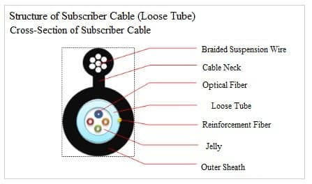
| TT | Name | Description | |
| 1 | Number of colored optical fibers | 1FO/2FO/4FO | |
| 2 | Liquid tube | Material Polybutylene terephthalate (PBT) | |
| Outer diameter ≥ 1.8 mm | |||
| Inner diameter 1.2 mm ± 0.1mm | |||
| Filling compound Thixotrophic Jelly Compound | |||
| 3 | Suspension wire | Steel wire 7 zinc-coated steel strands ( Ф ≥ Ø 0.33mm x 7 strands) | |
| Cable neck size ≥ 0.5×0.5 (mm) | |||
| Coating layer PE plastic, thickness ≥ 0.5 mm | |||
| 4 | Outer sheath | Material PE plastic | |
| Average thickness 1.0 mm ± 0.1mm | |||
| Reinforcement component Aramid Yarn | |||
Cable Jacket and Reinforcement
- The outer jacket is made of high-quality PE material, not recycled plastic, containing carbon for UV resistance, suitable antioxidant for oxidative resistance, non-fungal growth, and insulating ability.
- The cable jacket protects the cable core from mechanical impacts and environmental influences during storage, installation, and operation (water, temperature, chemicals, insect damage, etc.).
- The cable jacket is smooth, concentric, without joints, cracks, holes; uniformly of high quality (no roughness, bubbles, delamination, cracks, swelling, defects); metal-free; flexible, robust, and easy to strip.
- The PE jacket tightly hugs the buffer tubes and can be easily separated from the tube elements without affecting the fiber cable quality.
- Separating the hanging wire from the cable core does not alter the cable core structure or affect the fiber quality.
Fiber Color Coding
Fiber color code follows TIA/EIA-598-A standard as shown in the table below
| Number of Optical Fibers | Color of Optical Fibers |
| 1 | NA (any color) |
| 2 | Next color of fiber 1 in the color code table |
| 3 | Next color of fiber 2 in the color code table |
| 4 | Next color of fiber 3 in the color code table |
Optical Fiber Specifications
Optical and geometric characteristics of single-mode optical fiber according to ITU-T G.652.D and TCVN 8696:2011 recommendations.
| Parameter | Unit | Target | Method |
| Attenuation Coefficient | dB/km | ≤ 0.3 at 1550nm | IEC 60793-1-40 |
| ≤ 0.4 at 1310nm 1625nm | |||
| Dispersion Coefficient | ps/nm.km | ≤ 3.5 at 1310nm ≤ 18 at 1550nm | IEC 60793-1-42 |
| PMD Coefficient | ps/km¹/² | ≤ 0.2 | IEC 60793-1-42 |
| Zero Dispersion Wavelength | nm | 1300 ≤ λ₀ ≤ 1324 | IEC 60793-1-42 |
| Dispersion Slope | ps/nm².km | ≤ 0.092 | IEC 60793-1-40 |
| Cut-off Wavelength | nm | λcc ≤ 1260 | IEC 60793-1-44 |
| Bending Loss r (radius) = 30mm x 100 turns | dB | ≤ 0.1 at 1625nm | IEC 60793-1-47 |
| Mode Field Diameter | μm | 9.2 ± 0.4 at 1310nm | IEC 60793-1-45 |
| Mode Field Eccentricity | μm | ≤ 0.5 | IEC 60793-1-20 |
| Cladding Diameter | μm | 125 ± 0.7 | IEC 60793-1-20 |
| Cladding Non-Circularity | % | ≤ 0.7 | IEC 60793-1-20 |
| Coating Diameter | μm | 245 ± 10 (uncolored) 250 ± 10 (colored) | IEC 60793-1-21 |
| Splice Loss Increase | dB | 0.1 | IEC 60793-1-40 |
| Fiber Tensile Strength | Gpa | ≥ 0.69 | IEC 60793-1-30 |
Optical and geometric characteristics of single-mode optical fiber according to ITU-T G.657.A1 and TCVN 8696:2011 recommendations.
| Specification | Unit | Targets | Method | |
| Attenuation Coefficient | dB/km | ≤ 0.3 at 1550nm | ≤ 0.3 at 1490nm | IEC 60793-1-40 |
| Dispersion Coefficient | ps/nm.km | ≤ 3.5 at 1285nm to 1330nm | ≤ 18 at 1550nm | IEC 60793-1-42 |
| PMD Coefficient | ps/km¹/² | ≤ 0.2 | IEC 60793-1-42 | |
| Zero Dispersion Wavelength | nm | 1300 ≤ λ₀ ≤ 1324 | IEC 60793-1-42 | |
| Dispersion Slope | ps/nm².km | ≤ 0.092 | IEC 60793-1-40 | |
| Cut-off Wavelength | nm | λcc ≤ 1260 | IEC 60793-1-44 | |
| Bending Loss | dB | ≤ 0.25 at 1550nm | ≤ 0.1 at 1625nm | IEC 60793-1-47 |
| Mode Field Diameter | μm | 8.6 ± 0.4 at 1310nm | IEC 60793-1-45 | |
| Mode Field Eccentricity | μm | ≤ 0.5 | IEC 60793-1-20 | |
| Cladding Diameter | μm | 125 ± 0.7 | IEC 60793-1-20 | |
| Cladding Non-Circularity | % | ≤ 1.0 | IEC 60793-1-20 | |
| Coating Diameter | μm | 245 ± 5 | IEC 60793-1-21 | |
| Splice Loss Increase | dB | 0.1 | IEC 60793-1-40 | |
| Fiber Tensile Strength | Gpa | ≥ 0.69 | IEC 60793-1-30 | |
| Primary Coating Layer | Material resistant to ultraviolet radiation (acrylate), minimizing environmental impact. | |||
| Before coloring, the nominal diameter is 245 μm ± 10 μm, after coloring, the nominal diameter is 250 μm ± 10 μm using time-resistant ink. | ||||
| When splicing, the primary coating layer should be easily removable from the fiber without the need for chemicals and without affecting the fiber. | ||||
Physical, Mechanical, and Environmental Properties of Cable
| no | TEST | TEST METHODS AND STANDARDS | STANDARD | RESULT |
|---|---|---|---|---|
| 1 | Tensile Strength | IEC 60794-1-2-E1 | Drum diameter: ≥ 30D (D= cable diameter) Continuous load test: 500N for 5 minutes. | No cable sheath breakage, no fiber breakage, anoenuation increase: ≤ 0.2dB (at wavelengths 1310nm,1490nm,1550nm), wire elongation not exceeding 0.25% |
| 2 | Compression Resistance | IEC 60794-1-2-E3 | Test force: 100N/1cm for 1 minute and 50N/1cm for 10 minutes Number of test points: 1 | No cable sheath breakage, no fiber breakage, anoenuation increase: ≤ 0.2 dB (at wavelengths 1310nm,1490nm,1550nm). |
| 3 | Impact Resistance | IEC 60794-1-2-E4 | Hammer height: 100cm; Hammer weight: 0.3kg; Hammer head diameter: 25 mm Number of test points: 25 points (spaced 10cm apart) | No cable sheath breakage, no fiber breakage, anoenuation increase: ≤ 0.2 dB (at wavelengths 1310nm,1490nm,1550nm). |
| 4 | Bending Resistance | IEC 60794-1-2-E6 | Bending axis diameter: ≥ 20D (D = Cable diameter) Bending angle: ± 90°; Number of cycles: 25 cycles | No cable sheath breakage, no fiber breakage, anoenuation increase: ≤ 0.2 dB (at wavelengths 1310nm,1490nm,1550nm). |
| 5 | Twist Resistance | IEC 60794-1-2-E7 | Twist test length: ≤ 2m; Number of cycles: 10 cycles Twist angle: ± 180°; Axial load 40N | No cable sheath breakage, no fiber breakage, no sheath cracking when viewed through a magnifying glass up to 5 times |
| 6 | Heat Resistance | IEC 60794-1-2-F1 | Thermal cycle: 23°C ® -30°C ® +60°C ® 23°C Time at each cycle: 24 hours | Anoenuation increase: ≤ 0.2dB/km (at wavelengths 1310nm, 1490nm, 1550nm). |
| 7 | Flow Test of Filling Compound | IEC 60794-1-2-E14 | Test sample length: 0.3m, one end stripped of cable sheath approximately 80mm and hung upside down in the test chamber Test duration: 24h; Test temperature 60°C | The filling compound in the test sample does not flow down; The optical fibers in the loose tube remain in place without falling. |
| 8 | Water Penetration Resistance | IEC 60794-1-2-F5 | Test sample length: 3m; Water column height: 1m Test duration: 24 hours | No water penetration through the test sample |
Physical, Mechanical, and Environmental Properties of Cable
- Maximum tensile force during cable construction (short-term) must be at least 500N.
- Permissible tensile force during use is greater than 30% of the maximum tensile force during construction.
| Specifications | Specifications |
|---|---|
| Maximum allowable load during installation | 500N |
| Maximum allowable load during operation | 400N |
| Compression resistance | ≥ 500N/10cm |
| Temperature range during installation | -5°C ~ 65°C |
| Temperature range during operation | -10°C ~ 65°C |
| Minimum allowable bending radius during installation | 10 times the cable diameter |
| Minimum allowable bending radius after installation | 20 times the cable diameter |
| Maximum continuous cable length during installation | 2000m |
| Maximum continuous cable length during operation | 2000m |
Span and Sag
- With a span of ≤ 50m and a sag of 1%.
Packaging and Marking
a. Cable marking and length
- Cable information is marked at each meter length according to IEEE P1222 standard. Additional information can be added as per customer requirements.
Packaging
- Average length of cable: 3000m
- Cable is wound on wooden cable drums (with a length of 3000m).
- After testing, both ends of the cable reel are tightly wrapped to prevent water ingress.
- The cable drum face is marked with the following information.
Other Characteristics
- Cable jacket ensures solid protection for cable core (buffer tubes), hanging wire steel twist in installation operation.
- No protruding steel wire core, cable core when stripping/cutting the hanging wire.
- Cable service life >= 10 years
Document Details Download here