LLDPE Tight Buffer Drop Cable
Short Description:
TECHNICAL STANDARDS OF LLDPE TIGHT BUFFER DROP CABLE
PRODUCT DESCRIPTION
TECHNICAL STANDARDS OF LLDPE TIGHT BUFFER DROP CABLE
General Introduction
- Telecommunication network.
- Fiber to the home (FTTx-Sq)
- Subscriber network.
- Internet network.
Fiber Sign
- G.657.A1
- G.652.D
- G.657.A2
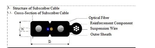
1. Structure of FTTx-Sq Drop Cable
| Specifications | |||
|---|---|---|---|
| No. | Name | Description | |
| 1 | Number of colored optical fibers | 1FO/2FO/4FO | |
| 2 | Additional reinforcement component | Single zinc-coated steel wire Ø ≥ 0.4mm | |
| 3 | Suspension wire - Galvanized steel wire | Braided steel wire (Ø ≥ 0.33mm x 7 strands) | |
| 3 | Suspension wire - Sheath | LLDPE plastic Average thickness 0.5 mm ± 0.1mm | |
| 4 | Outer sheath - Material | LLDPE plastic | |
| 4 | Outer sheath - Average thickness | 0.8 mm ± 0.1mm | |
1. Cable Jacket and Reinforcement
| Characteristic | Standard |
|---|---|
| Specific Gravity (ASTM D 1505) | ≥ 0.196g/cm³ |
| Tensile Strength (ASTM D 638) | ≥ 16Mpa |
| Elongation (ASTM D 638) | ≥ 500% |
| UV-resistant LLDPE material |
2. Fiber Color Coding
The fibers are color-coded according to the standard.
| Number of optical fibers in the optical subscriber line | Fiber color in optical subscriber line | |
| 1 | NA (any color) | |
| 2 | Next color of fiber 1 in the color code chart | |
| 3 | Next color of fiber 2 in the color code chart | |
| 4 | Next color of fiber 3 in the color code chart | |
3. Optical Fiber Parameters
The optical fiber parameters meet the standards of G.657.A1, G.652.D, and G.657.A2.
| Specifications | ||||
| Unit | Targets | Measurement methods | ||
| dB/km | ≤ 0.3 | IEC 60793-1-40 | ||
| Attenuation Coefficient | ||||
| ps/nm.km | ≤ 18 at 1550nm | IEC 60793-1-42 | ||
| Dispersion Coefficient | ||||
| ps/km^1/2 | ≤ 0.2 | IEC 60793-1-42 | ||
| PMD Coefficient | ||||
| nm | 1300 ≤ λ₀ ≤ 1324 | IEC 60793-1-42 | ||
| Zero Dispersion Wavelength | ||||
| ps/nm^2.km | ≤ 0.092 | IEC 60793-1-40 | ||
| Dispersion Slope | ||||
| nm | λcc ≤ 1260 | IEC 60793-1-44 | ||
| Cut-off Wavelength | ||||
| dB | ≤ 0.25 at 1550nm | IEC 60793-1-47 | ||
| Bending Loss r (radius) = 15mm x 10 turns | ||||
| dB | ≤ 0.75 at 1550nm | IEC 60793-1-47 | ||
| Bending Loss r (radius) = 10mm x 1 turn | ||||
| µm | 8.6 ± 0.4 at 1310nm | IEC 60793-1-45 | ||
| Mode Field Diameter | ||||
| µm | ≤ 0.5 | IEC 60793-1-20 | ||
| Mode Field Eccentricity | ||||
| µm | 125 ± 0.7 | IEC 60793-1-20 | ||
| Cladding Diameter | ||||
| % | ≤ 1.0 | IEC 60793-1-20 | ||
| Cladding Non-Circularity | ||||
| µm | 245 ± 10 | IEC 60793-1-21 | ||
| Outer Coating Diameter | ||||
| dB | 0.1 | IEC 60793-1-40 | ||
| Splice Loss Increase | ||||
| Gpa | ≥ 0.69 | IEC 60793-1-30 | ||
| Fiber Tensile Strength | ||||
| The primary coating layer uses UV-resistant material (acrylate), minimizing environmental impact. | ||||
| Primary Coating Layer | ||||
| The primary coating layer before coloring has a nominal diameter of 245 µm ± 10 µm, after coloring it has a nominal diameter of 250 µm ± 10 µm, using time-resistant ink. | ||||
| When splicing, the primary coating layer should be easily removable from the fiber without the need for chemicals and without affecting the fiber. | ||||
4. Physical, Mechanical, and Environmental Properties of Drop Cable
The cable meets the physical, mechanical, and environmental properties as per the standards.
| TEST | TEST METHOD AND STANDARD | Result | ||||
| Tensile Strength | IEC 60794-1-2-E1 | No cable sheath breakage, no fiber breakage, attenuation increase: ≤ 0.2dB (at wavelengths 1310nm, 1490nm, 1550nm), wire elongation not exceeding 0.25% | ||||
| Tensile Strength | IEC 60794-1-2-E3 | No cable sheath breakage, no fiber breakage, attenuation increase: ≤ 0.2 dB (at wavelengths 1310nm, 1490nm, 1550nm) | ||||
Physical, Mechanical, and Environmental Tests:
| Maximum allowable load during installation | 500N |
| Maximum allowable load during operation | 400N |
| Compression resistance | ≥ 500N/5cm |
| Temperature range during installation | -5°C ~ +65°C |
| Temperature range during operation | -10°C ~ +65°C |
| Minimum allowable bending radius during installation | 10 times the cable diameter |
| Minimum allowable bending radius after installation | 20 times the cable diameter |
6. Tensile Load of Optical Drop Cable
The tensile load test ensures the cable's durability.
7. Span and Sag
The span and sag parameters meet the required standards.
8. Packaging and Marking
The packaging and marking follow the industry standards.
9. Packaging
The cables are packed in wooden drums or as per customer requirements.
10. Other Characteristics
The cable has other specific characteristics that meet the standard requirements.
Detail Document