- This standard includes general optical and structural requirements for suspended optical cables containing 48 and 96 optical fibers manufactured by Recoin Electronics Telecommunications Joint Stock Company.
- The optical fiber used is single mode - step refractive index and is made of high quality glass material according to recommendations ITU-T G.652.D and TCVN 8665: 2011
- Cable lifespan: ≥ 15 years
- Cable types and cable symbols
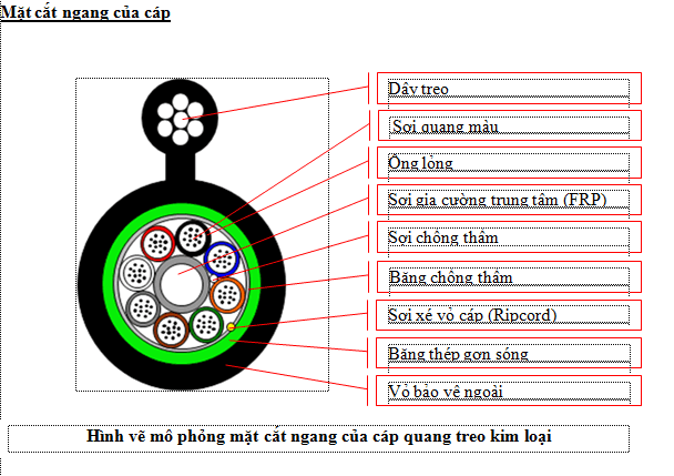
- Figure 8 metal-sheathed fiber optic cable 96FO, Symbol: TKL1 – LT8 – 96FO
- Figure 8 metal-sheathed hanging fiber optic cable 48FO, Symbol: TKL1 – LT4 – 48FO
- Figure 8 non-metallic sheathed fiber optic cable, Symbol: TPKL1 – LT8 – 96FO
- Figure 8 non-metallic sheathed fiber optic cable, Symbol: TPKL1 – LT4 – 48FO


Tên | Describe | |
Number of optical fibers | 48FO/96FO | |
Number of optical fibers in 1 loose tube | 12FO | |
Loose Pipe - Materials | PBT (Polybutylene terephthalate) | |
Loose tube - Outside diameter | ≥ 2.0 mm, always round and even | |
Liquid tube filling compound | Thixotrophic Jelly | |
Filler tube (if any) - Materials | PE plastic (or equivalent), no recycled plastic used, same size as loose tube, no defects | |
Central reinforcement component - Materials | FRP (Fiberglass Reinforce with Palstic) | |
Central reinforcement member - Diameter | ≥ 2,0 mm | |
Waterproof ingredients - Waterproof fibers | Water Blocking Yarn | |
Waterproof component - Waterproof tape and creates an even roundness for the cable core | Water Blocking Tape | |
Core braiding method | SZ reversible braid. | |
Rip cord (Ripcord) | Made of Aramid fibers that are tightly tied together to easily distinguish from other components and ensure it is strong enough to strip the cable sheath. Located under corrugated steel tape for metal cables. | |
Mechanical protection for metal cables | Corrugated steel tape, ripple height 0.5mm. | |
Fiber redundancy | Minimum 1% of the cable length at a temperature range of 20°C to 30°C | |
Outer shell - Materials | Black HDPE plastic | |
Outer shell - Thickness | 2,0 mm ± 0,1mm | |
Cable hanging wire - Galvanized steel wire | Consists of ≥ 7 galvanized steel strands braided together with diameters:\n- 48FO cable, diameter of each strand ≥ 1.0mm;\n- 96FO cable, diameter of each strand ≥ 1.2mm; | |
Cable slings - Size and cover of slings | Made of seamless HDPE plastic with cable cover, thickness and size:\n- Sheath thickness: ≥ 1.0mm;\n- Hanging neck height: 2.3mm ± 0.3mm\n- Neck width hanging wire: 2.3mm ± 0.3mm | |
1.The number, color of liquid tubes, and quantity of loose tubes and filler tubes comply with the provisions in the following table:
| Loose tube | Cable core element (loose tube/filled tube) | ||||||||
| TT | 1 | 2 | 3 | 4 | 5 | 6 | 7 | 8 | |
| Blue | Orange | Green | Brown | Grey | White | Red | Black | ||
| Cable core element (loose tube/filled tube) | |||||||||
| TT | 1 | 2 | 3 | 4 | 5 | 6 | 7 | 8 | |
| Number of optical fibers | 48FO | 12 | 12 | 12 | 12 | Padded | Padded | ||
| Cable core element (loose tube/filled tube) | |||||||||
| TT | 1 | 2 | 3 | 4 | 5 | 6 | 7 | 8 | |
| 96FO | 12 | 12 | 12 | 12 | 12 | 12 | 12 | 12 | |
TT | Target name | Standard | Measurement methods |
1 | Fiber Attenuation Coefficient (Attenuation Coefficent) | ≤ 0.35 dB/km\n≤ 0.36 dB/km\n≤ 0.21 dB/km\n≤ 0.22 dB/km | IEC 60793-1-40 |
2 | Dispersion coefficient | ≤ 3,5 ps/nm×km ≤ 18 ps/nm×km | IEC 60793-1-42 |
3 | Polarization Mode Dispersion (PMD) | ≤ 0,2 ps/ | IEC 60793-1-48 |
4 | Wavelength with zero dispersion (λ₀min – λ₀max) | 1300nm ≤ λ₀ ≤ 1324nm | IEC 60793-1-42 |
5 | Zere dispersion slope – S₀max | ≤ 0,092 ps/nm²×km | IEC 60793-1-40 |
6 | Cut–off wavelength λcc (Cut–off wavelength) | ≤ 1260nm | IEC 60793-1-44 |
7 | Loss when bending optical fiber at wavelength 1625nm (Marcro bending loss) with radius r = 30mm × 100 turns | ≤ 0,1 dB | IEC 60793-1-47 |
8 | MFD (Mode Field Diameter) mode field diameter at wavelength 1310nm | 9,2µm ± 0,5µm | IEC 60793-1-45 |
9 | Core concentricity error | ≤ 0,6µm | IEC 60793-1-20 |
10 | Cladding diameter | 125µm ± 1,0µm | IEC 60793-1-20 |
11 | Cladding noncircularity | ≤ 1 % | IEC 60793-1-20 |
12 | Primary coating diameter | 245µm ± 10µm 250µm ± 10µm | IEC 60793-1-21 |
13 | Point Discontinuity increases dramatically at wavelengths 1310nm and 1550nm (Point Discontinuity) | ≤ 0,05dB | IEC 60793-1-40 |
14 | Fiber tension | ≥ 0,69Gpa (100kpsi) | IEC 60793-1-30 |
15 | Fiber color code | Theo EIA/TIA-598 | |
16 | The primary shell uses a material that resists the effects of ultraviolet rays (acrylate), minimizing the impact of the external environment. | ||
17 | The primary shell before dyeing has a nominal diameter of 245µm ± 10µm, after dyeing it has a nominal diameter of 250µm ± 10µm using a durable ink over time. When applying, wipe off the gel around the fiber with 90° alcohol without discoloration | ||
18 | When welding is performed, the primary shell can be easily separated from the fiber without using chemicals and without affecting the fiber. |
| 1 | Fiber Attenuation Coefficient (Attenuation Coefficent) | ≤ 0,35 dB/km ≤ 0,36 dB/km ≤ 0,21 dB/km ≤ 0,22 dB/km | IEC 60793-1-40 |
| 2 | Dispersion coefficient | ≤ 3,5 ps/nm×km ≤ 18 ps/nm×km | IEC 60793-1-42 |
| 3 | Polarization Mode Dispersion (PMD) | ≤ 0,2 ps/ | IEC 60793-1-48 |
| 4 | Wavelength with zero dispersion (λ₀min – λ₀max) | 1300nm ≤ λ₀ ≤ 1324nm | IEC 60793-1-42 |
| 5 | Zere dispersion slope – S₀max | ≤ 0,092 ps/nm²×km | IEC 60793-1-40 |
| 6 | Cut–off wavelength λcc(Cut–off wavelength) | ≤ 1260nm | IEC 60793-1-44 |
| 7 | Loss when bending optical fiber at wavelength 1625nm (Marcro bending loss) with radius r = 30mm × 100 turns | ≤ 0,1 dB | IEC 60793-1-47 |
| 8 | MFD (Mode Field Diameter) mode field diameter at wavelength 1310nm | 9,2µm ± 0,5µm | IEC 60793-1-45 |
| 9 | Core concentricity error | ≤ 0,6µm | IEC 60793-1-20 |
| 10 | Cladding diameter | 125µm ± 1,0µm | IEC 60793-1-20 |
| 11 | Cladding noncircularity | ≤ 1 % | IEC 60793-1-20 |
| 12 | Primary coating diameter | 245µm ± 10µm 250µm ± 10µm | IEC 60793-1-21 |
| 13 | Point Discontinuity increases dramatically at wavelengths 1310nm and 1550nm (Point Discontinuity) | ≤ 0,05dB | IEC 60793-1-40 |
| 14 | Fiber tension | ≥ 0,69Gpa (100kpsi) | IEC 60793-1-30 |
| 15 | Fiber color code | According to EIA/TIA-598 | |
| 16 | The primary shell uses a material that resists the effects of ultraviolet rays (acrylate), minimizing the impact of the external environment. | ||
| 17 | The primary shell before dyeing has a nominal diameter of 245µm ± 10µm, after dyeing it has a nominal diameter of 250µm ± 10µm using a durable ink over time. When applying, wipe off the gel around the fibers with 90° alcohol without discoloration | ||
| 18 | When welding is performed, the primary shell can be easily separated from the fiber without using chemicals and without affecting the fiber. |
| TT | Targets | Test methods and standards | |
| 1 | Ability to withstand tension | IEC 60794-1-2-E1 | Roller diameter: ≥ 30D (D = Cable diameter)\nLength of test pulling cable section is ≤ 100m\nTest pulling time is maintained for 10 minutes\nContinuous test load:\n+ Corresponding to the weight of 1km of cable × 1 .2 for metal cable car\n+ Corresponding to the weight of 1km of cable × 1.5 for non-metal cable car |
| Result | Fibers are not broken, cable sheath is not cracked.\nIncreased attenuation: ≤ 0.1 dB, elongation ≤ 0.25% | ||
| 2 | Compression resistance | IEC 60794-1-2-E3 | Compress the cable between two steel plates, one fixed and one movable 10cm long. The radius of the edge of the mobile steel plate is about 5mm\nRepresentative sample with enough length to install on the machine.\nTest force: corresponding to the weight of 1 km of cable in 10 minutes.\nNumber of test points: 1 point. |
| Result | Fibers are not broken, cable sheath is not cracked.\nIncreased attenuation: £ 0.1 dB\nCompression cracks do not pose a danger to cable components. | ||
| 5.3 | shock resist ability | IEC 60794-1-2-E4 | Hammer height: 100 cm; Hammer weight: 1.0 kg\nHammer head diameter: 25 mm\nNumber of test points: 25 points (10 cm apart) |
| Result | The fiber is not broken, the cable cover is not cracked. Impact traces are considered normal.\nAttenuation gain: £ 0.1 dB | ||
| 5.4 | Ability to withstand bending | IEC 60794-1-2-E6 (hoặc E11) | Bending shaft diameter: ≤ 20D (D = cable diameter)\nBending angle: ± 90°; Speed: 2s/time; Load: 10kg; Number of cycles: 25 cycles |
| Result | The fiber is not broken, the cable cover is not cracked.\nIncreased loss: ≤ 0.1 dB." | ||
| 5.5 | Torsion resistance | IEC 60794-1-2-E7 | Twist test length: 4m; Number of cycles: 10 cycles.\nHelix angle: ± 180°; Axial load 100N. |
| Result | – Fiber is not broken, cable sheath is not cracked.\nIncreased loss: ≤ 0.1 dB; | ||
| 5.6 | Heat resistance | IEC 60794-1-2-F1 | Thermal cycle: +23°C ® -30°C ® +65°C ® +23°C\nTest sample length: ≥ 500m\nTest time at each thermal cycle is 24h\nEach specific thermal cycle is as follows following:\n– The starting and ending points are room temperature: 23°C\n– Time from +23°C to -30°C is 3 hours\n– Holding at -30°C is 6 hours \n– Increase from -30°C to +65°C in 6 hours\n– Hold at +65°C in 6 hours\n– Decrease temperature from +65°C to +23°C in 3 hours |
| Result | Attenuation gain: < 0.05 dB/km | ||
| 5.7 | Test the flow of the filling compound | IEC 60794-1-2-E14 | Test sample length: 0.3 m, one end has the cable sheathed approximately 80mm and hung upside down in the test chamber, the upper end is covered\nTest time: 24 hours;\nTest temperature: 60°C ± 5°C |
| Result | The filler in the test sample does not flow or fall out or the contents of the filler leak out < 0.05g.\nThe optical fibers in the loose tube stay in place and do not fall. | ||
| 5.8 | Waterproof ability | IEC 60794-1-2-F5 | Sample length: 3m; Water column height: 1m\nTest time: 24 hours at 25 ± 2°C |
| Result | Water does not penetrate through the test sample | ||
| 5.9 | Ability to withstand discharge voltage | TCN 68-160:1998 | Minimum voltage is 20 kVDC or 10 kVACrms with frequency 50~60Hz for 5 minutes |
| Result | The cable cover is not punctured | ||
| TT | Specifications | Targets |
| 1 | Maximum allowable range | 100m |
| 2 | Maximum allowable load during installation | 2.700N |
| 3 | Maximum allowable load when working | 900N |
| 4 | Temperature range when installed | -5°C ~ +65°C |
| 5 | Working temperature range | -10°C ~ +65°C |
| 6 | Minimum bend radius when installed | 10 times the cable diameter |
| 7 | Minimum bend radius after installation | 20 times the cable diameter |